
6502 FORTH, Part 4: Basic I/O
Published:
I’ve been posting about creating a Forth interpreter for a 65c02, and at this point I’m pretty close to something that could be tested. However, I still need one more piece of infrastructure before I can begin writing and testing my Forth interpreter: some way to communicate with a user.
My 6502 build includes a 65C22 VIA and 65C11 ACIA for general I/O and serial connections, respectively. The first step was to write some way to receive data over a serial connection. I found the datasheet at this link, and started to figure out how to get my computer to interact with the world around it.
Serial Connections
The 65C51 ACIA adapter is a pretty nifty little device–it even includes an onboard baud rate generator (this is why the computer requires a 1.8432 MHz external clock). The Symon simulator I’m using maps the ACIA to addresses $8000-8004, and examples from their Github use a baud rate of 9600. The actual code to make this work is significantly less daunting than I expected.
ACIA = $8000
ACIA_RX = ACIA         ; high here allows reading, low allows writing
ACIA_TX = ACIA
ACIA_STATUS = ACIA+1   ; Goes low when an interrupt occurs (?)
ACIA_COMMAND = ACIA+2
ACIA_CONTROL = ACIA+3  ; resets

reset_acia:
  pha
  ; ACIA setup
  lda #$00
  sta ACIA_STATUS       ; writing anything to status resets the chip
  lda #$0B
  sta ACIA_COMMAND
  lda #$1E
  sta ACIA_CONTROL
  pla
  rts
This initial implementation is based off of Michael Billington’s original post. There’s quite a few random hardcoded values in here, so let’s break them down based on the information in the datasheet.
Starting with reset_acia, we push and pull to the a register at the beginning and end of the subroutine to preserve whatever was in the A register when we started. In the middle, we load three seemingly random values into three registers. The ACIA has four main addresses accessible to our computer: R/TX, STATUS, COMMAND, CONTROL. The first of these is the register that receives and transmits data depending on if we read or write to it (resp.). We’ll come back to that register later.
The STATUS register is the simplest: the value at this address contains status of the ACIA device. Writing any value to this address resets the chip, which is why we start by writing $00 to it. The other bits of note in this address are bits 3 and 4, which correspond to the the receiver/transmitter data registers being full/empty (resp.). This will come in handy in our read/write methods later on.
Next is the COMMAND register. This register, when written to, changes how the ACIA handles data. Bits 5-7 control parity check controls, bit 4 changes the receiver between normal and echo mode, and bits 0-3 change if interrupt signals are sent when sending data (and if so, how they’re sent). I had initially planned to use these interrupt signals to trigger interrupts when data is ready to be read/written, but unfortunately I found out from this forum post that the 65C51 ACIA has a hardware bug that renders all the interrupts essentially unusable. Instead, we’ll have to disable them and rely on the 65C22’s clock to trigger interrupts. For the COMMAND register, we’re loading the value $0B = 0000 0111, corresponding to “Parity checks disabled”, “Normal Receiver mode”, “All interrupts disabled, receiver/transmitter enabled”.
Finally, we have the CONTROL register, which controls how the ACIA works. Bit 7 controls number of stop bits, bits 5-6 control the length of each data word, bit 4 controls the clock source for generating baud rate, and the lower 4 bits control the baud rate. We load a value of $1E = 0001 1110, corresponding to “1 stop bit”, “8 bit data word”, “Baud rate generator”, “9600 baud”. If we wanted to process at 19200 baud, we would instead set the value to $1F.
Once we’ve set up the ACIA, we can write some methods to read data from the chip:
acia_read:
  lda #$08
acia_rx_full:
  bit ACIA_STATUS       ; check to see if buffer is full (bit 3 is 1 if not empty)
  beq acia_rx_full
  lda ACIA_RX
  rts
Remember from before that bits 3 and 4 correspond to if the chip is ready to read/write. A 1 in bit 3 corresponds to a value of 0000 0100 = $08, so we do a bitwise comparison between $08 and the STATUS register to see if the data are ready to read. If they are, we read the value. beq acia_rx_full will branch if the result is 0, meaning if the STATUS register does not have a 1 in the third bit. If it does, the result is not zero and we can read the value out of the read register.
The method to send data is very similar, just with an additional operation to store the character in the a register while we check if we’re ready to write.
acia_send_char:
  pha
  lda #$10              ; %0001 0000, bit corresponding to write ready
acia_tx_full:
  bit ACIA_STATUS
  beq acia_tx_full
  pla
  sta ACIA_TX
  ;jsr delay_once_via    ; this delay is recommended to fix 65C51 transmit bug
  rts
Notice there’s a method commented out here. As mentioned before, a hardware bug prevents us from using the 65C51’s internal clock, which is unfortunate. Instead, I set up the 6522 VIA to send continuous interrupts at a timespan equivalent to the 6551’s baud rate. Without waiting a little bit after each transmission, we can get corrupt data or duplicated bytes. Unfortunately, the Symon emulator does too good a job replicating the performance of the machine, and so they don’t seem to have this error at all. As a result, I’m going to skip this for now and revisit it in the future when we get to hardware.
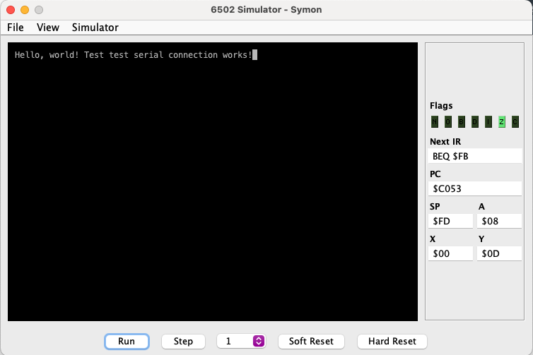
Testing the Serial Connection
It’s time for everyone’s favorite program: the Hello World script. For now, I’m just going to hardcode a text string to print, then have the program print the string. After this, it’ll echo back any input given over the serial connection.
main:
  jsr reset_acia
  jmp printstringtest
mainloop:
  jsr acia_read
  sta $00
  jsr acia_send_char
  lda $00
  jmp mainloop

printstringtest:
  ldy #0
nextchar:
  lda message,y
  beq mainloop
  jsr acia_send_char
  iny
  jmp nextchar

message:
  .aasc "Hello, world!"
  .dsb 1,0
Most of this code is pretty simple–we just initialize the ACIA chip, jump to a method to print out “Hello, world!”, then return and start echoing back characters. The message initializer stores an ascii string corresponding to the text string, then .dsb 1,0 fills the byte 0 immediately after the string. This makes the string null-terminated, so we can iterate over it by using lda message,y until the value loaded in a is zero. This can be checked with beq, and once we reach the end of the string we jump out of the loop to mainloop. At this point, we just alternate between reading and sending characters forever.
I also wanted to start writing code as if it’s going into the ROM chip, since eventually I’d like this to be loaded into the system from ROM. To do this, I’d need to compile my code so that the file is exactly 16 KiB. Additionally, I’d like to be able to set the beginning of the program and correctly link nmi and irq handlers to the right addresses ($FFFA and $FFFE, with $FFFC-D the start of the program).
This caused some issues, since xa lacks a .org command and has very sparse documentation. I found a post from the original developer of xa, but unfortunately it was from 2005 and the syntax has been updated since then. However, I was able to figure out the following syntax based on the docs and the 2005 post:
* = $C000

; ... code goes here

.dsb $fffa-*, $ea
.word nmi
.word reset
.word irq
This begins by initializing the program counter to $C000, which is the start of the ROM address space. The original suggestion was to use .byte $fffa-*, $ff, but .byte is no longer a command in xa. However, we can instead use .dsb, which specifies a data block to be filled with a particular value. The first part of the command, $fffa-*, specifies that the size of the fill block should be $fffa minus the value of the program counter, meaning the width of the space between the end of the code and $fffa. The second value is the value to fill the blocks with, which in this case is just $ea (which corresponds to a nop instruction). The final three lines fill the last 3 bytes of the program space with addresses for nmi, reset, and irq.
The complete test code looks like this:
* = $C000

main:
  jsr reset_acia
  jmp printstringtest
mainloop:
  jsr acia_read
  sta $00
  jsr acia_send_char
  lda $00
  jmp mainloop

printstringtest:
  ldy #0
nextchar:
  lda message,y
  beq mainloop
  jsr acia_send_char
  iny
  jmp nextchar

message:
  .aasc "Hello, world!"
  .dsb 1,0

.dsb $fffa-*,$ea
.word nmi
.word ROMSTART
.word irq
ROMSTART is just a constant set to $C000, which I’ve defined in a constants file.
If we compile and hexdump this, we can see that it is actually 16KiB, occupying memory from addresses $0000-3FFF. These will be mapped to $C000-FFFF, so this is all working correctly.
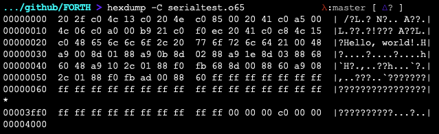
After this, we just need to run the program!
Adding Text Buffers
This setup is not bad, but it’s far from ideal. Since the maximum transmission rate of the ACIA is 19,200 baud, with this current implementation we’re limited to sending one character every ~0.53ms. With my current setup, the computer will have to wait between each of these send/receives, meaning that it can’t do any work in the meantime. It would be nice if we could just precalculate what we want to send over serial, and then process it when the ACIA has time. Likewise, if we send input, we don’t want the computer to have to process it immediately character by character.
To solve this, I’m going to set up a pair of buffers for input/output. I’ll write outgoing text to the $7Dxx memory page, and I’ll write incoming text to the $7Exx page. This way, I can store a string of up to 255 characters prior to having to send it out, and I can receive up to 255 characters before I have to process them with code. My constants file is getting a little large, so I’ll include it here:
;;;
;;; Constant values imported in other files
;;;

VIA = $8000
ACIA = $8800
DELAYCOUNT = $02F9  ; 7 before program counter (4 byte number)
ROMSTART = $C000

IPT1 = $4C
IPT2 = $4D
OPT1 = $4E
OPT2 = $4F

IPTBUFF = $7E00
OPTBUFF = $7D00
I’ve also defined four pointers, corresponding to the start and end of each buffer. One pointer will be incremented as the buffer is read/written to, and the other as the buffer is written/read from. This results in a minor modification to the ACIA software, including two new helper functions:
; These methods control the ACIA's side of read/write
; limited by baud transfer rate, can be blocking
acia_send_char:
  phy
  lda #$10              ; %0001 0000, bit corresponding to write ready
  ldy OPT2              ; load current place in buffer
acia_tx_full:           ; this loop will eventually be removed
  bit ACIA_STATUS       ; we can just check for full ACIA buffer on interrupts
  beq acia_tx_full
  lda OPTBUFF,y         ; write value in current place in buffer
  inc OPT2              ; then advance pointer
  sta ACIA_TX
  ;jsr delay_once_via   ; this delay is recommended to fix 65C51 transmit bug
  ply
  rts

; same as acia_send_char, just for reading
acia_read_char:
  phy
  lda #$08              ; %0000 1000, bit corresponding to read ready
  ldy IPT2
acia_rx_full:
  bit ACIA_STATUS       ; check to see if ACIA buffer is full
  beq acia_rx_full      ; this loop will eventually be removed
  lda ACIA_RX
  sta IPTBUFF,y
  inc IPT2
  ply
  rts

; These methods control writing/reading to the buffer
; can be done at anytime, non-blocking
acia_wbuff_char:
  phy
  ldy OPT1              ; load offset location of buffer
  sta OPTBUFF,y         ; store value in write buffer
  inc OPT1              ; increment offset pointer
  ply
  rts

acia_rbuff_char:
  phy
  ldy IPT1
  lda IPTBUFF,y
  inc IPT1
  ply
  rts
Because we’re now using a buffer to read/write, the test program changes slightly.
* = $C000
main:
jsr reset_acia
jmp buffstringtest
mainloop:
jsr acia_read_char ; read to buffer from ACIA
jsr acia_rbuff_char ; read from buffer to A register
jsr acia_wbuff_char ; write from A register to buffer
jsr acia_send_char ; write from buffer to ACIA
jmp mainloop
buffstringtest:
ldy #0
buffnextchar: ; write string to buffer
lda message,y
beq sendstring
jsr acia_wbuff_char
iny
jmp buffnextchar
sendstring: ; send string from buffer
lda OPT1
cmp OPT2
beq mainloop
jsr acia_send_char
jmp sendstring
message:
.aasc "Hello, world!"
.dsb 1,0
.dsb $fffa-*,$ff
.word $00
.word ROMSTART
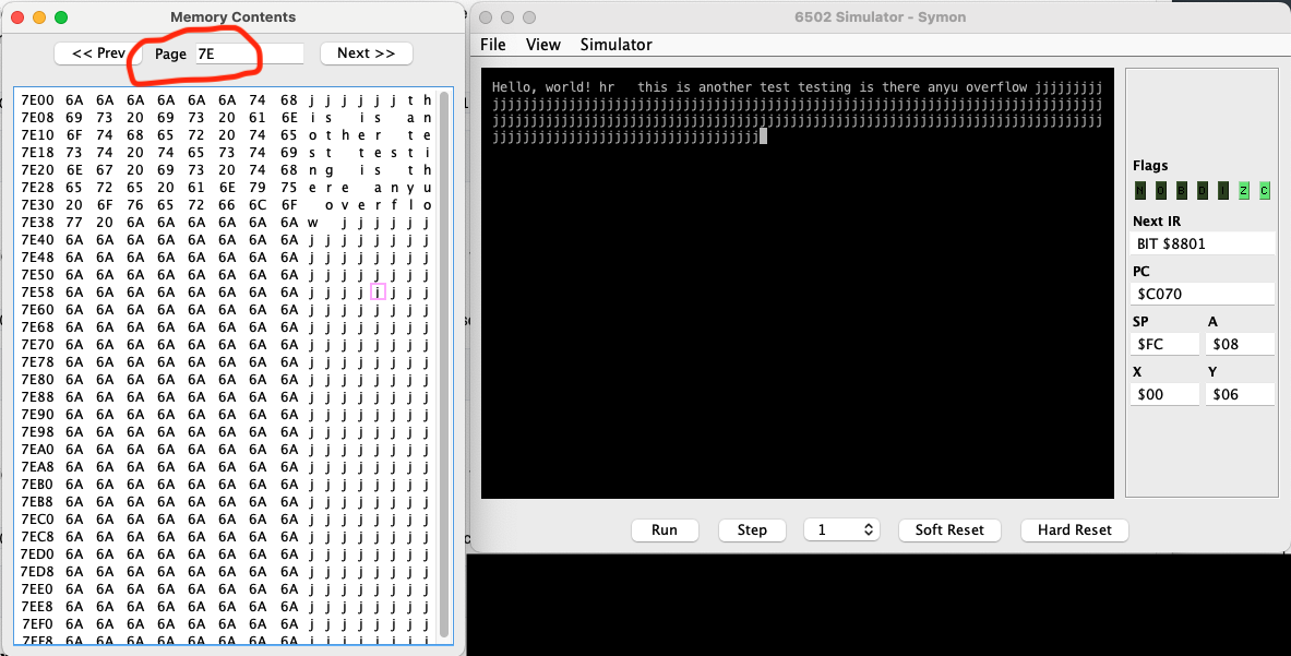
.word $00Shown below is an example output, along with the memory map for page $7E to illustrate that the buffer is getting filled up. I typed a bunch of j’s to verify that the buffer correctly rolls back to $7E00 from $7EFF.
Next Steps
I now have a way to send and receive data from the computer! I know there will be problems down the line with hardware bugs that I can’t replicate on the simulator, but I’m confident I’ll be able to troubleshoot that when I get there. Additionally, we don’t have any way to use arrow keys, backspace, or return/newline, but that can be handled later when I write the interpreter interface. For now, it’s finally time to start testing the Forth interpreter.